Configuration
In this lab we will configure IS-IS to carry IP routes. The IS-IS Lab Files include the initial and final configs for the topology.The router R2 will summarise the IP’s of the loopback interfaces into a /22 network.
The topology is as follows:
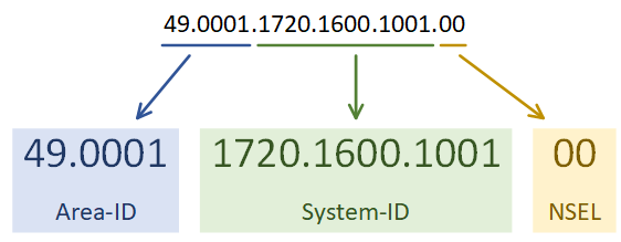
The first step is to enable the IS-IS process. Each IS-IS area uses a separete process. In the example below, the System-ID uses the IP address of Loopback 0 in the NET value. This could be any value, but reformatting a loopback IP makes troubleshooting easier.
The use of passive-interface is the same as with any other routing protocol.
The first IS-IS process on Cisco routers are set to Level 1-2. All later processes are Level 1 by default. Change this with the is-type command.
Following this, enable IS-IS on an interface.
[rtbs name=”isis_intro-configure”]
Show clns neighbours
confirms that neighbour relationships have been established.
Show isis database
shows the LSDB.
This is router reachability information.
Show clns interface
shows the IS-IS settings for the interface.
[rtbs name=”isis_intro-adjacency”]
We can see that IS-IS has learned routes, and installed them into the routing table.
[rtbs name=”isis_intro-routingtable”]
Under the IS-IS process, a summary address can be configured.
If a default route were required, it could be advertised with default-information originate.
Configure Summarization
R2(config)#router isis
R2(config-router)#summary-address 10.0.0.0 255.255.252.0 level-2
You can see that R3 is now learning the summary address, rather than each individual network.
Verify R3 Routing Table
R3#show ip route isis
Gateway of last resort is not set

      10.0.0.0/22 is subnetted, 1 subnets
i L2     10.0.0.0 [115/20] via 192.168.20.1, 00:03:15, GigabitEthernet0/1
      172.16.0.0/32 is subnetted, 3 subnets
i L2     172.16.0.1 [115/20] via 192.168.20.1, 00:19:51, GigabitEthernet0/1
i L2     172.16.10.1 [115/10] via 192.168.20.1, 00:19:51, GigabitEthernet0/1
      192.168.10.0/30 is subnetted, 1 subnets
i L2     192.168.10.0 [115/20] via 192.168.20.1, 00:19:51, GigabitEthernet0/1

 When IS-IS is on broadcast media, one router is the Designated Intermediate System, or DIS. The DIS will flood LSP’s out, instead of having all routers flood the segment. This is like the Designated Router in OSPF.